Home
/ 3 Way Switch Wiring Diagram Multiple Lights - How To Wire A 3 Way Light Switch Diy Family Handyman - All three switches are connected together by a three core and earth control cable.
3 Way Switch Wiring Diagram Multiple Lights - How To Wire A 3 Way Light Switch Diy Family Handyman - All three switches are connected together by a three core and earth control cable.
3 Way Switch Wiring Diagram Multiple Lights - How To Wire A 3 Way Light Switch Diy Family Handyman - All three switches are connected together by a three core and earth control cable.. One trick that i actually 2 to print the same wiring diagram off twice. Traveler wires are interchangeable on each switch. Notice that the wire connected to the com terminals is looped straight through. This is the one you need for nav lights. This circuit is wired the same way as the 3 way lights at this link.
It is not unusual for the wires inside of an outlet box to be covered by spray paint from the initial construction of a dwelling. Right now, each switch is functioning like a single pole, turning on/off the string of outlets rather than controlling the outlets as intended. Off/circuit 1/circuit 2 the other is off/circuit 1/ circuit 1&2. Light switch at one end, lights in the middle, light switch at the other end. Circuit 1 would be the anchor light, circuit 2 would be the red/green nav light.
Two Switches To One Light Wiring Multiple Lights 3 Way Switch Wiring Diagram Pdf Clipart Full Size Clipart 3369494 Pinclipart from www.pinclipart.com Circuit 1 would be the anchor light, circuit 2 would be the red/green nav light. Click the icons below to get our nec ® compliant electrical calc elite or electric toolkit, available for android and ios. This may be one of the most common way to wire a 3 way switch. Three way switching schematic wiring diagram. The same purpose can be achieved by using the following two way switching connection in fig 3 as well. Below is perhaps the simplest arrangement, panel to switch to switch to light: The white neutral wires are connected together in each switch box. Off/circuit 1/circuit 2 the other is off/circuit 1/ circuit 1&2.
Traveler wires are interchangeable on each switch.
Notice that the wire connected to the com terminals is looped straight through. It is also a good idea to watch some videos prior to installation to avoid unnecessary problems. Click the icons below to get our nec ® compliant electrical calc elite or electric toolkit. As with the other lighting diagrams in this section, the first ceiling rose could be a junction box instead, or could be connected via the 'loop at switch' method. The (orange) red wire is part of the 14/3 wire they used in diagram. Off/circuit 1/circuit 2 the other is off/circuit 1/ circuit 1&2. Traveler wires are interchangeable on each switch. Wiring 3 switches and 2 lights. Right now, each switch is functioning like a single pole, turning on/off the string of outlets rather than controlling the outlets as intended. It is not unusual for the wires inside of an outlet box to be covered by spray paint from the initial construction of a dwelling. 3 way switched outlet wiring. 3 way switch wiring diagram. It is only needed one time, as all other lights (only limited by wattage of switch) are run by 14/2 wire.
This circuit is wired the same way as the 3 way lights at this link. It is also a good idea to watch some videos prior to installation to avoid unnecessary problems. Below is perhaps the simplest arrangement, panel to switch to switch to light: The neutral is spliced to the white wire feeding the first fixture, via cable c1,where it is spliced to the neutral of both lights. When you make use of your finger or even stick to the circuit with your eyes, it's easy to mistrace the circuit.
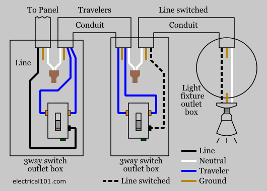
3 Way Switch Wiring Electrical 101 from www.electrical101.com When you make use of your finger or even stick to the circuit with your eyes, it's easy to mistrace the circuit. I'm wiring the new workshop and want to use 3 way switches to control four outlets running across the ceiling for plug in lights. Pick the diagram that is most like the scenario you are in and see if you can wire your switch! Light switch at one end, lights in the middle, light switch at the other end. 3 way switch wiring diagram. The circuit consists of a two way switch at each end (top and bottom switches in fig 2) and an intermediate switch in the middle. Click the icons below to get our nec ® compliant electrical calc elite or electric toolkit. All three switches are connected together by a three core and earth control cable.
Take a closer look at a 3 way switch wiring diagram.
Three way switching schematic wiring diagram. This circuit is wired the same way as the 3 way lights at this link. 3 way light switch with power feed via the light (two lights) the power, cable c1, joins the circuit at the light fixture f1. In this diagram, two 3 way switches control a wall receptacle outlet that may be used to control a lamp from two entrances to a room. Print the wiring diagram off and use highlighters to trace the routine. Think of your staircase or hallway. The hot from the power source is spliced through both fixtures and terminates at the common terminal of sw1 via cable c3. The neutral is spliced to the white wire feeding the first fixture, via cable c1,where it is spliced to the neutral of both lights. If the wire does not need to feed additional receptacles then you would not need the 14/3 and could just use a 14/2 in it's place. 3 way switched outlet wiring. More lights can be added to this circuit by duplicating the wiring shown here for each additional fixture. Light switch at one end, lights in the middle, light switch at the other end. The circuit consists of a two way switch at each end (top and bottom switches in fig 2) and an intermediate switch in the middle.
With these diagrams below it will take the guess work out of wiring. Pick the diagram that is most like the scenario you are in and see if you can wire your switch! The same purpose can be achieved by using the following two way switching connection in fig 3 as well. When autocomplete results are available use up and down arrows to review and enter to select. In this case, the end of the white wire from the light box to the.
Trying To Figure Out 3 Way Switch Loop Double Gang Multiple Circuits Wiring Doityourself Com Community Forums from www.doityourself.com 3 way switched outlet wiring. This is the one you need for nav lights. 3 way switch diagrams for multiple light fixtures: Three way switching schematic wiring diagram. The white neutral wires are connected together in each switch box. All three switches are connected together by a three core and earth control cable. Extending to three or more lights. Pick the diagram that is most like the scenario you are in and see if you can wire your switch!
Circuit 1 would be the anchor light, circuit 2 would be the red/green nav light.
Light switch at one end, lights in the middle, light switch at the other end. 3 way light switch with power feed via the light (two lights) the power, cable c1, joins the circuit at the light fixture f1. Pick the diagram that is most like the scenario you are in and see if you can wire your switch! Two switch box wiring image. As with the other lighting diagrams in this section, the first ceiling rose could be a junction box instead, or could be connected via the 'loop at switch' method. Take a closer look at a 3 way switch wiring diagram. Click the icons below to get our nec ® compliant electrical calc elite or electric toolkit. The hot source is connected to the common terminal of sw1. The same purpose can be achieved by using the following two way switching connection in fig 3 as well. Circuit 1 would be the anchor light, circuit 2 would be the red/green nav light. This drawing shows the wiring for multiple lights in a 4 way switch circuit with the source and fixtures coming before the switches. The circuit consists of a two way switch at each end (top and bottom switches in fig 2) and an intermediate switch in the middle. Touch device users, explore by touch or with swipe gestures.

